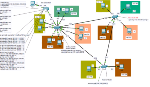
Imagine you are an entrepreneur and that you own a large office building with several routers. Because of various factors like an expanding need for space, clientele, or employees, you decide to rent a second office building across town. Suppose you want these buildings to act as one in terms of the way they interact with each other on a network. With a GRE tunnel, it is possible to logically turn two buildings full of networking equipment into one. Instead of having to operate a second geographical location as a separate entity, a GRE tunnel virtually connects each location in such a way that they act almost as if they were in the same building. Physically, the data still goes across the internet, but a header is added to the ethernet frames by the GRE tunnel that makes the two sides see the packets as if they belonged to the same network.
Perhaps you want all of the routers in your business to route to each other using various dynamic routing protocols like OSPF or EIGRP. With a GRE Tunnel, all of the devices can talk to each other and share LSA’s in order to find the best paths and load-balancing methods for all of the company data. Dynamic routing is one of the primary keys in determining the need for GRE Tunnels. If we were literally using the network above, GRE would probably be overkill and a waste of time and resources. Although there are two locations, there aren’t enough routers between the two of them to justify the need for a GRE tunnel. You likely won’t need a dynamic routing protocol with only two routers in the separate buildings.
However, imagine if PC1 in Office A tried to send packets to PC 3 in Office B. After arriving at R4, suppose there were five or six routers between them. The site network engineer at Office B could spend long hours setting up static routes between the devices, but this would be extremely tedious and time-consuming. The whole endeavor would lead to poor efficiency and time spent constantly updating static routes as data bottlenecks occurred. Setting up static routes is fine in networks with only one or two routers. If, however, the company has many routers GRE tunnels are way more convenient since they support dynamic routing protocols. OSPF and EIGRP are dynamic routing protocols supported by GRE and can make changes to routes automatically to find the shortest paths and perform load-balancing.
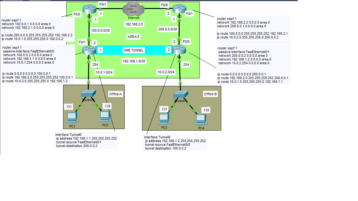
Typically, OSPF will use only one shared area called an autonomous system. The area in OSPF refers to a group of routers that share the same LSBD (Link State Database), where the routers have an individual map of the network necessary to configure the most efficient route. In an earlier post, I spoke of Dijkstra’s algorithm which was discovered as a means to use a nifty formula to calculate the shortest path from one LAN to another. In the case of this network, there is only one OSPF area, but you can set up many if needed. Additional OSPF areas would defeat the purpose of the GRE tunnel since its purpose is to keep everything congruent across two different physical locations.
If you have IPsec encryption configured (tunnel mode = header plus payload encrypted, transfer mode = only payload is encrypted), your devices can share a single public IP address so long as both locations use the same service provider. Public IP addresses are expensive, and it’s unlikely that a single company would need more than one for multiple locations.
Modern routers typically use a technique called PAT (port address translation) to recycle the same public IP address with a one-to-many IP scheme which differentiates the public IP address with random port numbers. Your home router very likely performs PAT to allow all the devices in your house to share a single public IP address.
The concept of tunnels in a network helps with client server data transfer. This is especially true if one office wants to have centralized servers for the entire company. Some companies prefer not to use cloud services to store their data. Many companies prefer to have their data servers use a tangible device that is close by for troubleshooting and easy access. A GRE tunnel can make the communication between different locations easier because it eliminates the need for multiple servers at multiple locations. Servers are also expensive, so GRE can save companies thousands of dollars in monthly cloud fees and equipment.
To configure a GRE tunnel, you will need to create a virtual tunnel interface on each of the adjacent routers. To do this, you would open the CLI of the Cisco router and go to global-config mode. You would then type the command ‘interface Tunnel0’. Once in interface config mode, you would set the IP address for the tunnel interface on R1 (192.168.1.1). You would then tell the router what the source physical interface the GRE tunnel is using to get to R2 (in the case of R1 F0/1). From there, you would specify the tunnel destination physical interface on R4 (F0/0). To complete the tunnel, you have to configure it the same but backwards on R4.
Note that there is a combination of static and OSPF routes on this network. You could probably get away with static routes alone with how straightforward the paths in this network are. However, we are assuming OSPF will be managing more routers than what’s displayed in this lab. A combination of static and dynamic routes would make more sense if I had made the network larger and more complex. Since this is just a demonstration, the simplicity can ironically be a bit confusing, but hopefully it gets my point across as to the purpose of GRE tunnels. I feel that I have achieved success if my audience at least has a general idea what I am trying to accomplish.
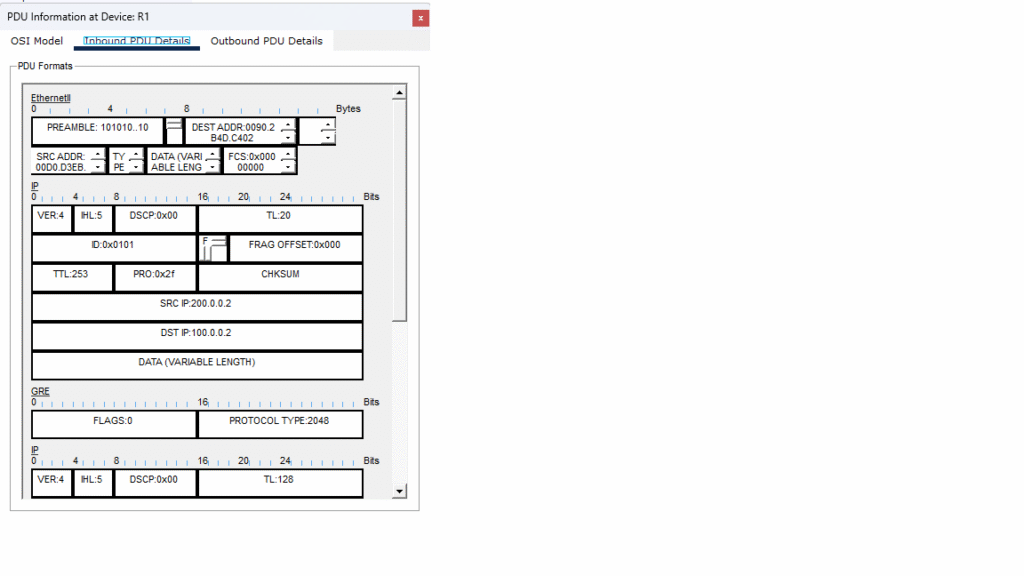

In the above images, I took snapshots of the frames as they reach R1 and R4 inbound and outbound on the configured interfaces. Outbound is when the ethernet frame goes from a device in Office 1 to R1 and from Office 2 to R4. Inbound is when Office 1 sends a frame and R4 has it inbound for Office 2. The opposite is true with inbound frames on R1. i performed a ping test in Packet Tracer to capture traffic as they traverse the GRE tunnel. Above you can see a GRE header below the IP header in the outbound frame, you can see the source and destination IP addresses as they correspond to the source interface F0/0 with 100.0.0.2 on R1 and destination interface F0/1 with 200.0.0.2 on R4. The inbound frame has the source and destination IP addresses reversed. This setup is not ideal as it is unencrypted and would typically use a protocol called IPsec to prevent the compromising of data across the internet.
I hope this article was helpful in understanding the purpose of GRE tunnels. While they aren’t very practical for small operations, one can see their importance as businesses grow and the need for consistent data flow via dynamic routing becomes a must. I have provided a link to this lab on my GitHub account for anyone who wants to look at it in Packet Tracer or play around with the configurations.