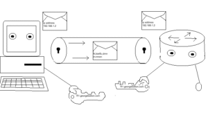
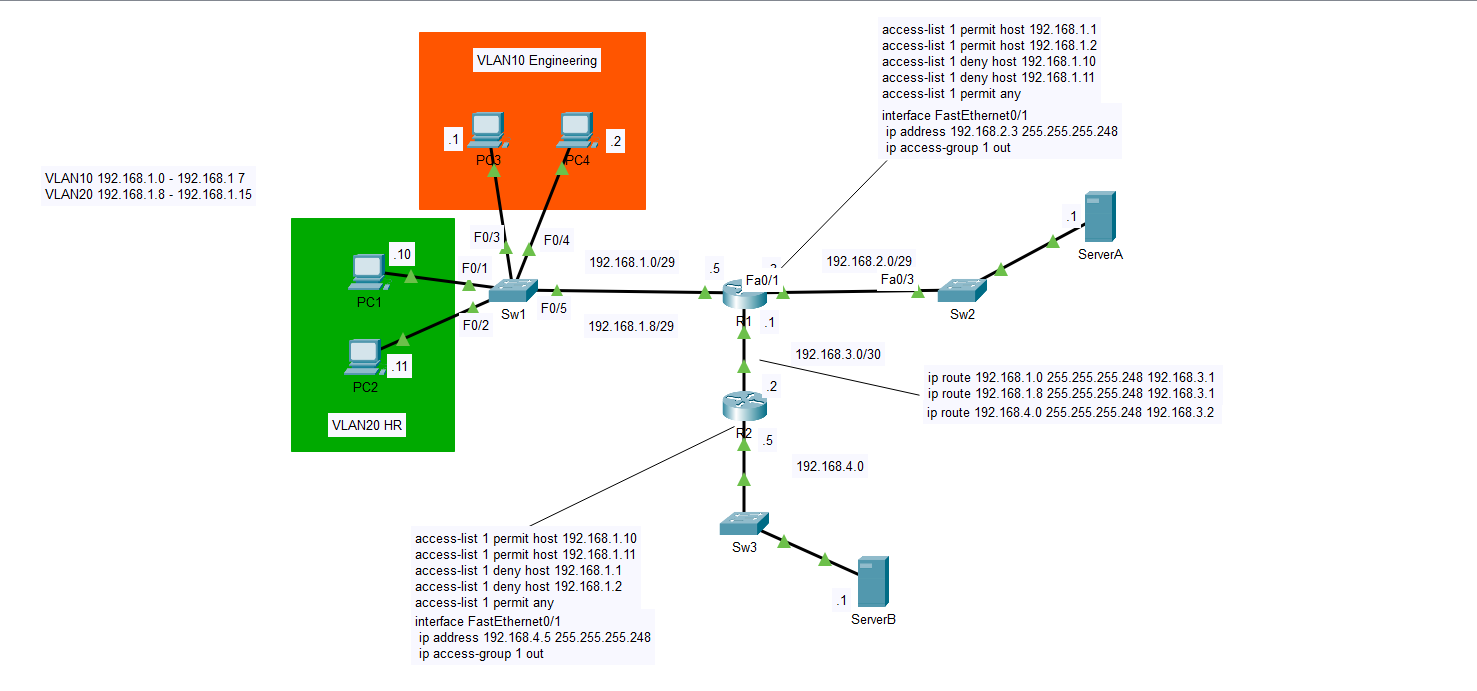
The next topic I will be discussing is standard ACLs or Access Control Lists. What exactly is an ACL and what is it used for? In this lab I will be discussing this helpful tool and how it can make things more convenient for us as network engineers. In the image above I have set up four computers on the right side of the diagram in the 192.168.1.0 subnet. The PCs .1 and .2 are in the Engineering department in VLAN10 and PCs .10 and .11 are in HR in VLAN20. Let’s suppose this network is part of a large company and that ServerA has detailed but also classified plans of the company’s network infrastructure. Maybe these plans contain crucial data that could compromise the company if the wrong people had access to it. Perhaps, we only want Engineering to access the plans on ServerA and not HR. ServerB likewise may have files that only HR should be able to access and not Engineering. For this, an ACL would act as a control point by which we can permit or deny access to these departments. With an ACL we can filter incoming traffic to each server by IP address and ensure that no unauthorized devices get past the ports configured with the standard ACL.
I’d first like to point out my use of VLANS in this lab. I may have added more complexity in doing so and it wasn’t necessary to put the PCs in different VLANs. Standard ACLs don’t filter traffic based on VLANs, but instead on the source IP address of the communicating device. One could just as easily apply an ACL that limits access coming from ServerA or B to any of the PCs on the left side of the diagram. Standard ACLs look only at the IP addresses associated with the clients. I could have decided to use two switches with one for Engineering, and the other for HR, but in a real-world environment extra switches aren’t cheap. If we can more cheaply separate network traffic using VLANs rather than additional switches to break up broadcast domains we should do it. When setting up standard ACLs, we should configure them on the port of the router closest to the end device we are trying to control access to. For ServerA we can see that R1 is the closest router and that interface Fa0/1 is the closest port. We first have to create the access list which defines the ACL rules before assigning it to a port.
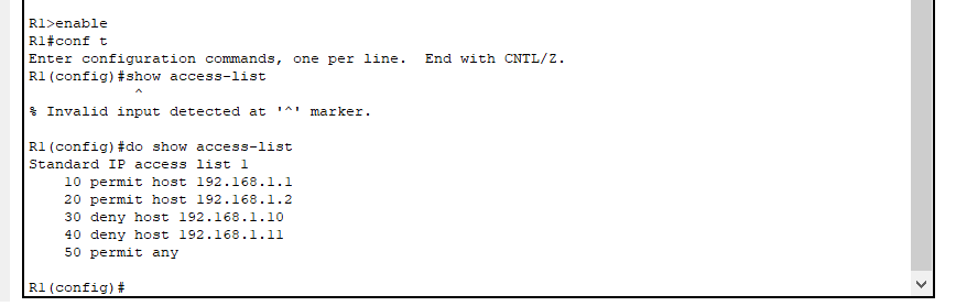
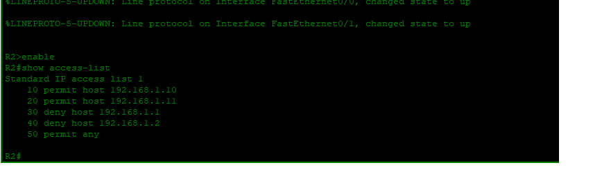
Above I have posted the CLI commands for the ACL. Once these commands are configured you can view them using the ‘show access-list’ command. The ACLs are ordered with a set of ACEs or Access Control Entries in this case from 10 to 50 with an increment of 10. The order of these ACEs is very important as the router reads them in order. The router will read that hosts 192.168.1.1 and .2 are permitted, then deny the .10 and .11 if those try to go through. Permit any is added at the end to ensure that the implicit deny doesn’t take affect and unnecessarily block traffic. Implicit deny is a default setting with standard ACLs that will deny any devices access if not specified if the last entry is left blank. This is why we include permit any. The command ‘deny any’ is unnecessary because of this rule. If we only want to block PC1 and PC2 but not all others, then adding permit any will override the implicit deny.
The ACL by itself doesn’t do anything unless you specify to which port it will be applied. A general rule is that you should apply the ACL to the port closest to the device of which the ACL references. In the case of ACL 1 on R1 we are referencing ServerA so the closest port on R1 is f0/1. To apply the ACL to F0/1 we must first go into interface config mode by the command ‘interface F0/1’, and then 0n the next line type ‘ip access-group 1 out’. This means that the ACL is assigned to all outbound that is out of the router traffic on R1. If the traffic being filtered was coming from ServerA then the command would be ‘ip access-group 1 in’. This command can be difficult to remember as we are talking about access-lists, but the command to apply it to an interface is ‘access-group’. If your command is coming up as invalid, be sure to check that the syntax you’re using is valid. Another trick if you are stuck is to use the ‘?’ command after the word ‘access’. This will show you a list of all possible valid commands that come after the specified word. if the command is invalid then you will not see any suggestions that match it. Make sure you use a space after the word before typing the question mark or it may not work. You can try both as I sometimes get mixed results.
In the diagram if you look at R2 you can see where I included the running configuration of interface F0/1 which is the closest one to ServerB. Included are the ACEs, the configured IP address, and the direction of the standard access list as it applies to F0/1. Like interface F0/1 on R1 the ACL is applied outward on R2’s F0/1 interface. With R2, we did the exact opposite of R1 allowing traffic from PC 1 and 2 and denying traffic from PC 3 and 4. All other traffic is permitted with the ‘permit any’ command. The key is knowing on which ports to configure the ACL and in what direction it should be done. Always apply standard ACLs on the port closest to the device to which you want to allow or deny access or else you might unnecessarily block traffic that needs to go through on a different port. if I had applied ACL 1 on R1, but inbound on the port facing the hosts PC1 and 2 would have no path to reach ServerB. You would allow PC3 and 4 access, but PC1 and 2 can’t even get into the router to go out a different gate. if they need access to a different part of the network. Be diligent with this rule and you won’t have any problems.
As noted earlier, remember that I added VLANs 10 and 20 that were unnecessary to the objectives of this lab. I added VLANs only because in a real network design doing so saves money as opposed to buying two switches and connecting them to two separate ports on R1. One other reason I added the VLANs was for practice on my part. If you ever decide to create your own blog, I think it’s a good idea to include vital principles of network design like VLANs for repetition configure elements f you are interested in understanding VLANs or point to point routing configurations then you can read my articles on those topics. I just wanted to give you a basic understanding of what standard ACLs are how they work, and some basic rules for configuring them. As always, click the link to the lab below that will take you to my GitHub account. Just make sure you have a Cisco Packet Tracer account and download the program. Feel free to play around with the configuration using simulation mode to ping and trace the packets. You might also check the running-configuration and try creating your own lab based on the information. Good luck, and have a great day.
georgebatton/Standard-ACLs: Configuring Rules for IP Traffic