We will now examine SSH or Secure Shell, a protocol designed for remote access to network devices. The concept of SSH is simple, but I found SSH configuration confusing at first. Suppose I have a router in another room and I want to configure it. One way to configure the device would be to grab my console cable and laptop, connect them, and open a program like ‘PuTTY’ or some other terminal emulator. From there, I would access the device’s CLI (command line interface) and make the necessary configuration changes and updates. In the old days, network engineers used a protocol called ‘Telnet’. Telnet allowed one to connect remotely to a network device, but the configuration information was transmitted in clear text. This meant that the data going from your remote host to the network device was unencrypted and open to hackers and other malicious parties interested in stealing your data. SSH addresses this problem by enabling encrypted remote management. The process of setting it up is more involved than with Telnet, but it becomes easier once you become familiar with the steps.
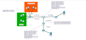
If I am on PC1 and I want to configure R1 without getting up, I would first have to set up SSH on R1. In this scenario, R1 acts as the server, and PC1 serves as the client. Whatever device you SSH into is the server, while the device that logs in is the client. It’s generally a good idea to create an ACL, or ‘Access Control List’, to prevent any unwanted clients from connecting to the devices.
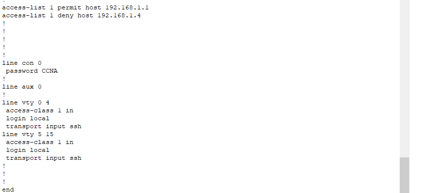
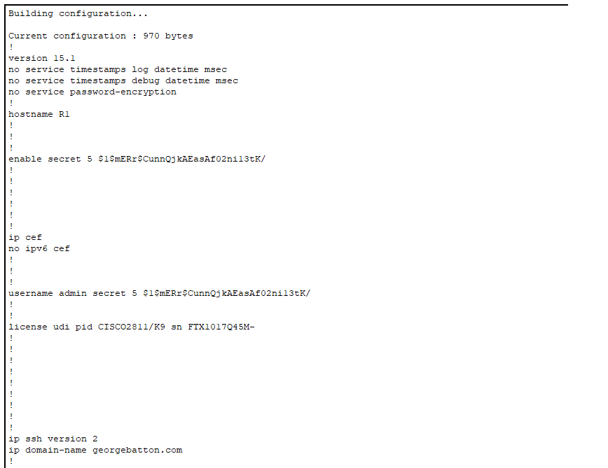
In this case, I granted access to PC1 via its IP address, 192.168.1.1, and denied access to PC4 at 192.168.1.4. To enter SSH configuration mode, we need to specify the VTY lines. I will allow lines 0-15, which allows up to 16 users to SSH into the device and view information. Only one user is allowed to make changes at a time. To enter this mode, we type ‘line vty 0 15’. To create the security keys necessary for the encryption tunnel between the server and client, we first need to create a hostname for the device. For this, I changed the default name ‘Router1’ to ‘R1’. I also made the domain name georgebatton.com. The running-configuration shows the commands I used to make this happen.
These are necessary steps because the crypto keys have a key name consisting of the hostname and domain name, or in this case, R1.georgebatton.com. Finally, we type ‘crypto key generate rsa’ to create the keys, enabling encryption over a secure tunnel. It’s a good idea to specify that the device uses SSH version 2 with the command ‘ip ssh version 2’. To make SSH work, we still need to create a login and a password. In this case, I entered global configuration mode and typed ‘username admin secret CCNA.’ I also need to type login local to denote that I’m using this username and password scheme. This will come into use when you need to log into the router from user exec mode.
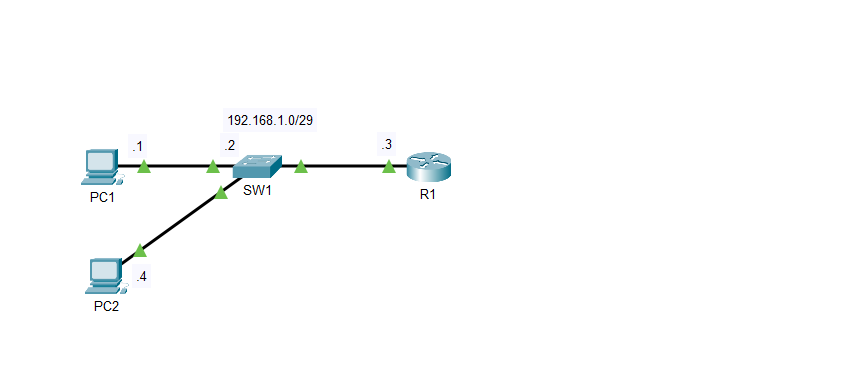
I will need the same password when going to user exec mode and beyond. To ensure the access control lists I created apply, I used the command ‘access-class 1 in’. SSH requires permission to work on R1, so the command ‘transport inut ssh’ should be placed at the end of the list of commands. To log into R1, I will open the command prompt on one of the PCs and type ‘ssh -l admin 192.168.1.3’. This is fine for a router, but layer two switches don’t have IP addresses. In this case, I created an IP address on the switch in a few steps. Once we do this, we can SSH into the switch in the same way as with the router. We first have to go to a Virtual LAN with the command ‘ int Vlan1’. This command enables us to assign an IP address to the VLAN on the switch. From here, we specify the IP address on the switch as 192.168.1.2. For the switch to work in conjunction with SSH, we need to specify the IP address of the default gateway, or in this case, R1, with the command ‘ip default-gateway’. On SW1, I configured my ACLs to be the opposite of R1, where PC4 is permitted for SSH, but PC1 isn’t. The rest of the SSH configurations are the same.

SW1 is set up with an ACL permitting access to PC2 but denying access to PC1 which is the opposite of how it is configured on R1. Since the switch isn’t a layer 3 device a vlan must be created to set up and IP address. As long as the subnet allows for the additional IP address this is a viable way to communicate with Layer 2 devices. With a /29 prefix we are allowed up to six usable hosts with two bits left over for the network and broadcast address. The command default-gateway 192.168.1.3 is necessary on the switch to point back to R1 for reference.

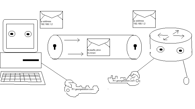
What we are doing essentially is creating an encryption tunnel from the PCs on the network to an SSH enabled device. The hostname forms the first part of the crypto-key, and the domain name creates the second part to share connectivity and access to this encryption tunnel. You can think of each device opening a door on either side to access port 22 where SSH resides. Telnet is on port 23 and requires no key because there is no locked encryption tunnel. Once the devices are recognized the ACL is checked and a password is verified. From here encrypted remote access is possible and engineers can work on the devices even from across the globe. I hope you enjoyed this short explanation of SSH. I know it’s not the most detailed description of all the processes, but I didn’t want to get too bogged down and overcomplicated. I just wanted to show you what SSH is and how you can set it up on network devices. Feel free to look at my GitHub lab at the link below: