What is Per VLAN spanning tree (PVST) and why do we use it? Per VLAN spanning tree is a Cisco proprietary protocol that works with classic and rapid spanning tree protocol allowing certain blocked ports in one VLAN to forward data in different VLANs while simultaneously preventing layer 2 loops. PVST takes advantage of vacant bandwidth on the network and allows different VLANs to use additional forwarding paths.
In a situation with three or more switches there is a potential for data to travel in a circle instead of in a straight line. When network traffic flows in a circle an endless loop can occur leading to what is called a broadcast storm. This is especially true during the initial broadcast when the switches are learning the MAC addresses of host devices on the network. Broadcast storms can overwhelm the CPUs of the switches and bring down the entire network.
In my example lab I have configured four separate VLANs with trunk links. Trunk links are single physical links that carry multiple VLANs with ISL or 802.1Q tags to differentiate them from other network traffic. VLANs are a convenient way to limit and segregate broadcast traffic from initial unknown unicast frames when establishing connections within a LAN. If a user in VLAN 10 for instance only wants his or her broadcast traffic to go to users in their department a VLAN can prevent the traffic from broadcasting beyond VLAN 10.
It’s good that our VLANs are only talking to one another when that’s intended, but it’s nice also to be able to talk to users outside of our VLAN if necessary. This is where inter VLAN routing or Router on a Stick (ROAS) can be a convenient choice. R1 is set as the means of routing between VLANs using sub-interfaces. This is the router’s means of mimicking and communicating with trunk ports on a switch. Instead of configuring a trunk port with allowed VLANs the router needs the interface configured with sub interfaces.
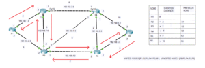
In many deployments there are instances where three or more switches are interconnected in a triangle or square topology creating the potential for layer 2 loops. In the diagram above there is a triangulation between the switches that could potentially cause a switching loop. Spanning-tree protocol prevents this by using an algorithm that selectively forwards data on some ports while blocking others. The six ports interconnecting the switches above are trunk ports. One port is selected as an alternate or blocked port to prevent loops. If a non-blocked port loses connectivity with any of the other switches, the spanning tree algorithm recalculates the port status. A blocked port becomes designated, and traffic will take an alternate route.
Per VLAN spanning tree allows different VLANs to forward data across multiple paths on trunk links. The spanning-tree algorithm is dependent ultimately on the value of the root bridge or switch of the VLAN. The root bridge is chosen by lowest bridge ID plus MAC address. The default bridge priority on Cisco switches is 32768. If the bridge IDs are equal, then the device with the lowest MAC address is chosen as the root bridge. The command ‘spanning-tree VLAN VLAN NUMBER priority PRIORITY NUMBER’ can be used to lower the priority of the root bridge in global configuration mode in the switch command line interface.
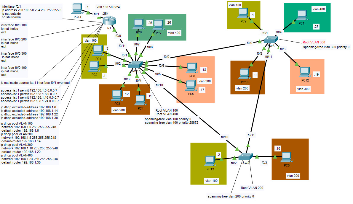
In VLANs 100 and 400 I configured SW1 as the root bridge by manually lowering their priorities and in VLAN 200 I made switch 2 the root bridge. Switch 3 is the root bridge for VLAN 300. From the root bridge all of the trunk ports are designated and in a forwarding state. This behavior can change if a hub is involved. Hubs are almost never used in modern networks so we can generally assume this behavior to be consistent. The two designated ports, therefore, will forward network traffic. The same is true no matter which switch is configured as the root bridge. Configuring different switches as the root bridge helps to ensure that traffic in each VLAN is using all possible routes and load-balancing across ports.
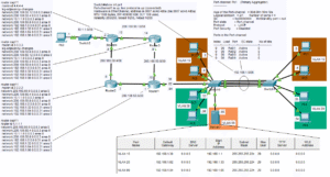
On R1 I configured the Router with port address translation and as a DHCP server. Each sub-interface is specified with an inside local configuration from a DHCP pool starting with the first available host IP address. Because each VLAN is part of a /29 subnet there are a total of 6 usable hosts including the default gateway. The outside global address is configured as 200.100.50.254. Port address translation maps a pool of private IP addresses to a single public IP address by using different port numbers to differentiate each simultaneous connection. For further details feel free to read my article on port address translation.
I have provided a link to this lab in GitHub if you wish to see the details of the configuration. When you get to the page click where it says view raw. You will be prompted to install Packet Tracer and set up an account if you don’t have one.: Per-VLAN-Spanning-Tree/VLANs.pkt at main · georgebatton/Per-VLAN-Spanning-Tree