
This Lab was quite a challenge. I wanted to demonstrate my understanding of VLAN connectivity not just between hosts, but also between routers. Virtual local area networks (VLANs) logically divide broadcast domains into smaller broadcast domains. A broadcast domain is where a device, like a switch, sends frames out all active ports, looking for a match to the destination MAC address it received from a host. When switches receive frames from hosts with no correlating destination MAC address in their CAM table, they treat them as unknown unicast frames. They then flood frames out all ports except the ones on which they were received. VLANs divide up this process by limiting the number of ports that flood the frame only to the interfaces specified. This reduces unnecessary network traffic and lessens potential security threats on the network. Another benefit of VLANS is that department-specific network traffic can be separated within a company. Each switchport assigned to a VLAN must be configured as an access port. Access ports are also known as untagged ports. This is because, unlike trunk ports, end hosts don’t care about VLAN IDs and automatically assume frames belong to them so long as the destination MAC address matches their own.
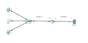
I configured a trunk port on each side of the network to connect the switch to the router. If only one cable is used the switches and routers need a way to differentiate between VLANs. I configured trunk ports on the switches on port F0/1 to connect to the routers on both sides of the network. Trunk ports can carry multiple VLANs across a single interface, unlike access ports. They can do this because of a protocol known as IEEE 802.1q. Also known as “dot1q”, IEEE 802.1q is an industry standard protocol that encapsulates or ‘tags’ VLAN frames in a trunk port. This is convenient because it’s always a good idea to conserve ports whenever possible.
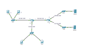
This particular configuration is called inter VLAN routing or ‘router on a stick’. Inter VLAN routing maintains the separateness of the VLANs created on the switch while using logical sub-interfaces on a router allowing for communication across separate VLANs. I created an additional option where if R2 determines that a frame isn’t for itself or any VLAN in its network, it will forward the frame to the next router (R1) in the point-to-point setup. I configured the point-to-point routes statically, as in the previous post about point-to-point connectivity. I was having trouble getting the two networks to talk to one another. In the previous lab it was easy because there were no VLANS or trunk ports to deal with. Sometimes, configuring this information can be confusing because you’re not sure what VLANs to allow on which trunk port, and what IP addresses to assign to the sub-interfaces etc. On both sides of the network I allowed VLANs 2-4 on both trunk links. The sub-interfaces only need to specify the VLANs in its own network. For instance, on the side with R1, only VLANs 2 and 4 are needed on the F0/1 interface on the router. On R2, VLANs 2 and 3 need sub-interfaces configured on port F0/1. The trunk ports needed all of the VLANs specified for it to communicate properly. Anyway, I feel free to look at the readme file and lab on my GitHub site. This is the link: georgebatton/InterVlan-Routing: Lab with 3 Vlans connected with 2 separate LANS
Thank you for bearing with me on this one. I know this isn’t the most exciting topic. I tend to get lost in jargon. CCNA topics can be pretty dry and aren’t the easiest things to explain to the lay person. I hope to continue to improve my writing skills and to make these posts more interesting and catered less exclusively to tech insiders.